At default 6400 step config settings I get a scan which, while object curves can be identified, consists of multiple images. Checked reference of stepper motor in kit and found it was 1.8 dev (200 step) rather than the expected 0.9 /400. Reduced setting to 3200 and then got duplicate scan. At 1600 get a recognisable image but low resolution. My background is computers, not board level electronics, so am stuck at present. Stepper driver is TMC2209 with stealth thing. I am finding references that might suggest that something needs to be jumpered / bridged, but I think this is the time to reach out and ask for any assistance that can be offered.
Twin laser setup, calibrated to death, all solder joints double checked
can you take a picture of your stepper and post your config file here. What version of the software are you using? I am asking because I had similar problems with the last stable version.
you can try: https://fabscan.org/community/latest-release/easy-change-of-the-version/#post-1730
Here is what I think I know on the subject.
The stepper controller board is normally set for 16 microsteps. Hence 3200 trigger pulses per 1 rotation of 1.8 degree 200 step motor. The present software 0.9.2 has 3 selections for resolution. Every 8 microsteps to stop for a scan of 400 vertical scans per revolution, 4 microsteps for 800 per revolution, or every microstep for 3200 scans per revolution. In the 2 units I have I am using a TMC2100. The microstep configuration pins are labeled CFG1, CFG2 and CFG3. Unfortunately I haven't found the logic levels required for the two different controllers but they are of the same family and I suspect they should be the same. I wonder if you changed the 3200 to 200 and the used the lowest resolution, is it possible to estimate your configuration microstep value from the number of degrees the turntable turns. Doesn't solve the problem but lets you know where you are. On my unit, I measure close to 4 volts peak to peak at 6300 hertz with a Sansmart DDS140 oscilloscpe on pins CFG1 and CFG2 of the driver board. a multimeter reads about 2.45 volts average.
An additional thought-at 200 in place of the 3200 in the default.config.json file I would expect 25 scans at the lowest resolution and if the rotation of the turntable is 360 degrees (one turn) there is no microstepping programmed on the driver board. The voltage measered on the CFG1 and CFG2 pins is not peak to peak but 0 to 4 volts measured with the oscilloscope.
The stepper controller board is normally set for 16 microsteps. Hence 3200 trigger pulses per 1 rotation of 1.8 degree 200 step motor. The present software 0.9.2 has 3 selections for resolution. Every 8 microsteps to stop for a scan of 400 vertical scans per revolution, 4 microsteps for 800 per revolution, or every microstep for 3200 scans per revolution. In the 2 units I have I am using a TMC2100. The microstep configuration pins are labeled CFG1, CFG2 and CFG3.
You are right. The default configuration of the HAT fits the TMC2100. Anyway you can make it work with other drivers too. You can find a listing with the driver settings for the TMC2209 here: https://learn.watterott.com/silentstepstick/pinconfig/tmc2209/
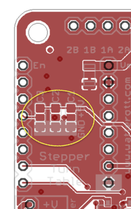
As you can see in the table at the bottom of the page you need to set the cfg pins to vio (aka 5v in our case) for 1/16 micro stepping. You can reach that by just configuring the cfg1/MS1, cfg2/ms2 pads on the HAT. You need to connect the middle cfg1 and cfg2 pad to the corresponding "+" pads (vio).
The "+" pads are those above the middle pad in the image.
I think that will do the trick. But you need to set the number of steps in your config according to your motor. 3200 steps for a motor with 200 steps per revolution and 6400 steps for a motor with 400 steps per revolution.
Thank you gentlemen! I have updated to 0.9.3 candidate and am getting much better results, though still at 1600. I am on a steep learning curve with the electronics and spent a lot of time yesterday reading up on stepper drivers and the picture is beginning to form....
Not quite sure I have the courage to get the soldering iron out just yet.
Would it be easier to buy a 2100??


