I have My FabScanner built, and mechanically its working. I used an Arduino Uno with a Pi 3, a single laser and a Pi V2 camera. I built my box from some old 70s style mid century teak veneer which looks great. Even though the FabScan is mostly working (after fixing a few bugs in the Arduino FW - which I will submit later), I can not get the scan data points to look correct. Can someone help me !
I calibrated my system, and the config file can be seen below (post calibration). I changed a few things in the default.config.json file, because my NEMA stepper motor has a resolution of 200, and is in 1/16th mode - so 3200 per complete single revolution, and the diameter of the turntable is 14 cm, so 70 mm radius :
turntable": {
"steps": 3200,
"radius": 70,
"height": 15,
"degree_per_step": {
"low": 3.6,
"medium": 1.8,
"high": 0.8
}
One thing with the above though is that the fabScan wiki help pages don't mention what degree of step - low, medium, high are for, or the height is for ?
I also changed the number of laser to 1 - single laser.
The non default camera settings are these - as my camera shows the image sideways (rotated 90 degrees) - so I changed vflip to True.
"rotate": "True",
"hflip": "False",
"vflip": "True",
The calibration values are the default values, apart from the origin-distance, which is 47mm from the turntable to the top of the bottom chessboard row, so I changed it to this
"pattern": {
"square_size": 11,
"rows": 6,
"columns": 8,
"origin_distance": 47,
"type": "chessboard"
},
These settings match my chessbaord calibration I printed off.
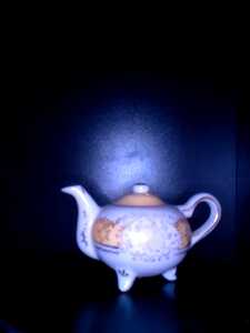
Following are pictures from my scans of a tea pot. Here is the original image from the first phase of calibration
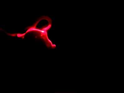
I noticed when I set the config to keep the scan images, that I can see the red laser outline and it looks correct - apart from the images are rotated 90 degrees - so imagine each picture is on its side 90 degrees rotated to the right with the top of the image on the right hand side of each picture.
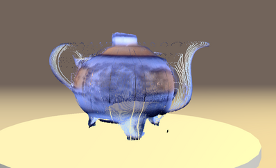
Also the cloud points are the same, when I rotate the cloud points in the web browser they dont rotate around the centre of the turn table, they rotate around a side view.
Is there a bug when you change the vflip ? Shall I rotate the camera physically to the correct orientation ? Then put the vflip back to false ?
This is the complete config file...
{
"folders": {
"www": "/usr/share/fabscanpi/",
"scans": "/home/pi/scans/"
},
"laser": {
"interleaved": "False",
"numbers": 1,
"color": "R (RGB)"
},
"scanner_type": "laserscanner",
"calibration": {
"weight_matrix": [],
"dist_camera_matrix": [],
"pattern": {
"square_size": 11,
"rows": 6,
"columns": 8,
"origin_distance": 47,
"type": "chessboard"
},
"camera_matrix": [
[
1523.29,
0.0,
625.986
],
[
0.0,
1532.168,
836.781
],
[
0.0,
0.0,
1.0
]
],
"distortion_vector": [
0.069,
1.188,
0.01,
0.002,
-5.062
],
"laser_planes": [
{
"distance": 137.20160911374415,
"normal": [
-0.5304927113828322,
0.00498085382173772,
0.8476748635325322
],
"deviation": 0.02480792209446897
}
],
"platform_translation": [
1.6427253799511443,
55.221398747460626,
161.43405393591323
],
"platform_rotation": [
[
0.0,
0.9999409321721393,
0.0108688622547649
],
[
0.002282825804996973,
0.010868833934311546,
-0.9999383266758267
],
[
-0.9999973943497773,
2.48117192261349e-05,
-0.0022826909634352877
]
],
"type": "chessboard"
},
"meshlab": {
"path": "/usr/bin/"
},
"process_numbers": 3,
"turntable": {
"steps": 3200,
"radius": 70,
"height": 15,
"degree_per_step": {
"low": 3.6,
"medium": 1.8,
"high": 0.8
}
},
"camera": {
"resolution": {
"width": 1640,
"height": 1232
},
"preview_resolution": {
"width": 800,
"height": 600
},
"rotate": "True",
"hflip": "False",
"vflip": "True",
"type": "PICAM",
"undistort": "False"
},
"connector": {
"type": "serial",
"firmware": "fabscanpi",
"baudrate": 57600,
"autoflash": "False",
"flash_baudrate": 115200,
"port": "/dev/ttyUSB0"
},
"texture_illumination": 160,
"keep_raw_images": "False",
"keep_calibration_raw_images": "False",
"discoverable": "True",
"online_lookup_ip": "8.8.8.8"
}


