to use modified Fab...
 
Notifications
Clear all

to use modified FabScan in the TU Darmstadt in the future

14 Posts
3 Users
2 Reactions
2,698 Views
shengchu
Posts: 7
Topic starter
(@shengchu)
Active Member
Joined: 5 years ago

Hi, Members of the FabScanPi,

I am a mechanical engineering student at TU Darmstadt. Our Institut PTU (Produktstechnik und Umformmaschinen) wants to build a 3D scanning system using turntable to scan small deep drawn aluminum parts. I have found the FabScanPi really close to our project, so it would be interesting for me that I can modify a FabScanPi to fit with our project, because my tutor wants to use only two industrial cameras without any laser.

For me it is important to know, how the RaspberryPi drives the turntable and how it interacts with the camera system. This project is also part of my bachelor thesis, it would be great if I can learn from you guys!

I am open for a conversation to provide more details!

Reply
13 Replies
mario
Posts: 570
Admin
(@mario)
Honorable Member
Joined: 6 years ago

Hi, 

Posted by: @shengchu

, because my tutor wants to use only two industrial cameras without any laser.

How do you want to perform a scan? How should the cameras be aligned? 

Posted by: @shengchu

to scan small deep drawn aluminum parts.

Keep in mind that metallic parts are hard to scan because of their shiny surface. You need to prepare the parts with chalk- or 3d scanning spray before you are able to scan. 

Generally all you need to do ist to customize the scanning module. Just do a copy of the laserscanner folder, rename it to what you want.

https://github.com/mariolukas/FabScanPi-Server/tree/master/src/fabscan/scanner/laserscanner

Then change the default.config.json. Just change "scanner_type": "laserscanner", to "scanner_type": "your-awesome-scanner". That is the way to create a custom scanner routine. The next part is the hardest part. You need to change the scanning routines to your needs. 

The main file ist https://github.com/mariolukas/FabScanPi-Server/blob/master/src/fabscan/scanner/laserscanner/FSScanProcessor.py

All scan performing steps are defined in this file. If you are planing to connect a custom camera, you need to modify the camera driver. 

https://github.com/mariolukas/FabScanPi-Server/blob/master/src/fabscan/scanner/laserscanner/driver/FSCamera.py

This driver is mostly written for the Raspberry Pi camera, but you can find some initial code which will run a generic usb camera. Change the camera type in the default.config.json from PICAM to USBCAM. But keep in mind that the usb camera driver is not a system driver. It is just providing an abstract capture interface to the FabScanPi HardwareController class. Maybe need also to install a kernel driver for your industrial cameras. Additionally you should implement a kind of camera multiplexer for capturing from two cameras. Best place to do that would be the hardware controller. 

https://github.com/mariolukas/FabScanPi-Server/blob/master/src/fabscan/scanner/laserscanner/FSHardwareController.py#L43

You need to instantiate a second cam. 

I recommend of thinking about a second camera. Maybe it would be better to turn the object and do a second scan with just one camera. Afterwards you can align both scans with a software like Meshlab or Cloudcompare. But generally using two cameras depends on the 3d scanning technic you want to perform ( laser scanning, photogrammetry scanning or stereo vision).

cheers 

Mario


Reply
shengchu
(@shengchu)
Joined: 5 years ago

Active Member
Posts: 7

@mario

Hallo Mario,

What do you mean about using two cameras? Do you think it is better to use stereo vision? For us it is important to maintain the edge information of a deep drawn cup (it looks kind of like rounded beer bottle hat, the shape and the size). Chalk and 3D scan spray will be used first to avoid reflection. The industrial cameras we have are Basler acA1600-60gm GigE Kamera ( https://www.baslerweb.com/de/produkte/kameras/flaechenkameras/ace/aca1600-60gm/#tab=specs)

I will use one horizontal camera to capture photos at the side to get the height of the edge of the cup while it is turning, and another camera that capture from above to get the radius information. I want to try first without using any lasers and pattern light to see if I can use computer vision algorithsm to extract edge data directly from the photo stream. Then, I will use the laser to see if the scanning method provides better quality. 

I wasnt sure about what you mean about using two cameras. Do you suggest that I should use stereo matching for the 3D reconstruction? Do you suggest that Picameras are suitable enough for the small object scanning?

If the Fabscan Pi costs totally 200 euro, I am thinking about talking to my tutor to purchase the Fabscan Pi and also the service of your team. We can run some experiment with your devices and do some optimization for our situation.


cheers

shengchu 


Reply
mario
Admin
(@mario)
Joined: 6 years ago

Honorable Member
Posts: 570

@shengchu

Posted by: @shengchu

What do you mean about using two cameras? Do you think it is better to use stereo vision? For us it is important to maintain the edge information of a deep drawn cup (it looks kind of like rounded beer bottle hat, the shape and the size). Chalk and 3D scan spray will be used first to avoid reflection. The industrial cameras we have are Basler acA1600-60gm GigE Kamera ( https://www.baslerweb.com/de/produkte/kameras/flaechenkameras/ace/aca1600-60gm/#tab=specs)

I will use one horizontal camera to capture photos at the side to get the height of the edge of the cup while it is turning, and another camera that capture from above to get the radius information. I want to try first without using any lasers and pattern light to see if I can use computer vision algorithsm to extract edge data directly from the photo stream. Then, I will use the laser to see if the scanning method provides better quality. 

I think i understand what you are trying to do. It sounds like a very interesting approach. Please keep us informed.

Posted by: @shengchu

Do you suggest that Picameras are suitable enough for the small object scanning?

Depends on the resolution/quality you want to reach. There are also pi cams with different cs mount lenses on the marked. I am already doing some tests.

IMG 20190731 220612


The hard part with using two cameras is that you need to multiplex the cams, for this you need additional hardware. I would suggest to use USB cams. Have a look at the code i linked above, this will give you a good starting point. I would love to see a working usb camera implementation. 

Posted by: @shengchu

If the Fabscan Pi costs totally 200 euro, I am thinking about talking to my tutor to purchase the Fabscan Pi and also the service of your team. We can run some experiment with your devices and do some optimization for our situation.

The Kit is available at Watterott. Unfortunately there is no big Team and no professional support behind the project. The project is a spare time and community based but you can get some help here.

- Mario 

Reply
Qaribpour
(@qaribpour)
Joined: 5 years ago

Active Member
Posts: 13

@shengchu

Hi shengchu

I wanna edit python backend codes, but I don’t know how can I access them, should I find them in SD card or should I follow another approach?


Thanks in advanced and regards,

Hossein


Reply
shengchu
Posts: 7
Topic starter
(@shengchu)
Active Member
Joined: 5 years ago

Hallo Mario,

I have ordered a fabscan pi to TU Darmstadt on watterott received the packet last week! This week I was trying to assamble it and I was excited to see how it would work! But during the assembling I met some problems and therefore I want to have an exchange of information with you, to see what the original designer thinks.

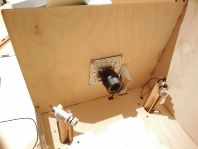
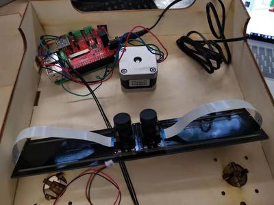
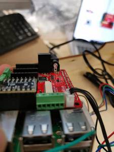
As you can see, I planed to use usb-binocular-cameras for the image acquisition, the problem here is with the fabscan pi. From the website of Fabscan pi https://fabscanpi-server.readthedocs.io/en/latest/hardware/#connecting-the-power-supply the power connector is at a different side as the image on the fabscan homepage. So I am a little bit confused on which one is the right orientation. If I solder it on the upper site, the Netzteil will be blocked by the motor, so I can never fit it in the box.
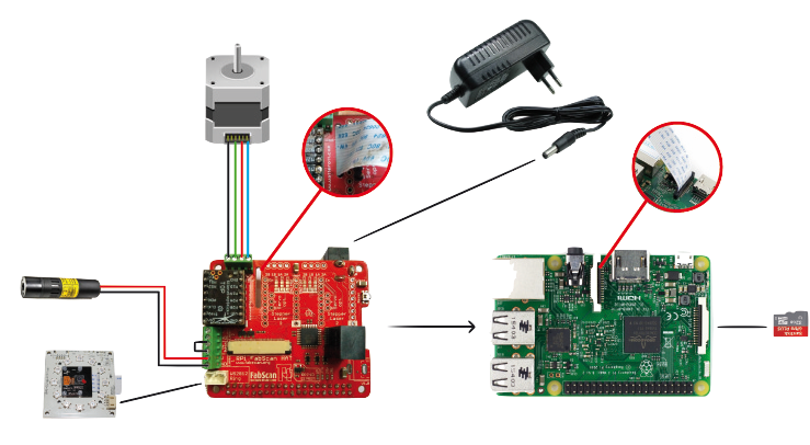
drawing_400

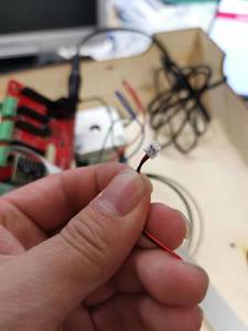
And also the laser wire has a white hat on it, which is different as the introduction. I think I have to remove the white hat so I can connect the laser with the Fabscan Pi HAT?

I am looking forward to your advice

cheers 

shengchu

 20191023170450
 20191023170512
 20191023170518


Reply
shengchu
Posts: 7
Topic starter
(@shengchu)
Active Member
Joined: 5 years ago

And btw, do i need to solder the regulator on the HAT? Or it is already sufficient that I just stick it in the HAT?

Reply
mario
Admin
(@mario)
Joined: 6 years ago

Honorable Member
Posts: 570

@shengchu

Posted by: @shengchu

And btw, do i need to solder the regulator on the HAT? Or it is already sufficient that I just stick it in the HAT?

Sorry for the late response, you should solder the regulator on the HAT. But if you think about using the Raspberry Pi 4 you need to add a standalone 5V power supply with min. 4000 mA. 

The white connector needs to be removed from the laser. 

Reply
shengchu
(@shengchu)
Joined: 5 years ago

Active Member
Posts: 7

@mario

No problem, I got your message. I have managed to assemble the whole fabscan pi. The connection via Ethernet to my laptop is successful, but the laser is not working as expected. I dont know where went wrong. I have removed the white connector and connected the laser to the HAT as in the video. But the Laser never shined, no matter how I press the on-and-off button on the 8080 browser interface.

Anyway, I might order another laser. Do you have any other suggestions? 

Reply
mario
Admin
(@mario)
Joined: 6 years ago

Honorable Member
Posts: 570

@shengchu

Have you bridged the connectors (security switch) in the middle of the laser connection screw terminal? Otherwise the laser is not powered. The terminal is for 6 connections. 2x laser ( left and right ones) and 1x security switch/ or power bridge (both in the middle). 

Reply
shengchu
(@shengchu)
Joined: 5 years ago

Active Member
Posts: 7

@mario

There was no security switch in the package, I was also wondering why the laser is not working. any suggestions to fix this problem?

Reply
mario
Admin
(@mario)
Joined: 6 years ago

Honorable Member
Posts: 570
Posted by: @shengchu

@mario

There was no security switch in the package, I was also wondering why the laser is not working. any suggestions to fix this problem?

That is correct. The switch is optional and that is why you need to bridge the connector. See "Connecting the Lasers" in documentation.

I think in your case it is better to connect the laser directly to a 5v voltage to proof if the laser is damaged. Then connect it to the board like it is described in the documentation. Check for the bridge. See "Safety Switch" section beyond the "Connecting the Lasers"

https://fabscanpi-server.readthedocs.io/en/develop/hardware_electronics.html#assemble-the-fabscanpi-hat

Reply
mario
Posts: 570
Admin
(@mario)
Honorable Member
Joined: 6 years ago
Posted by: @qaribpour

I wanna edit python backend codes, but I don’t know how can I access them, should I find them in SD card or should I follow another approach?

You should go from source. Go to e.g. /home/pi and checkout the current source to this location. 

git clone  https://github.com/mariolukas/FabScanPi-Server.git 

Then stop the running FabScanPi Server by 

/etc/init.d/fabscanpi stop

If you need to do more work on the code it would be a good idea to remove the fabscanpi server from the default runlevels. Otherwise it is started automatically if you reboot the Pi.

Next go to your checkout folder /home/pi/FabScanPi-Server. You are able to start the FabScanPi-Server Software from source. If you change some source stop the server and run it again. It is more convinient to use a PyCharm Pro license. This enables to use a IDE on your Computer and do remote debuging and running of the code on the Pi. 

For starting from source use: 

/home/pi/FabScanPi-Server/src/fabscanpi-server --config=/home/pi/FabScanPi-Server/src/fabscan/config/default.config.json  --settings=/home/pi/FabScanPi-Server/src/fabscan/config/default.settings.json  
Reply
shengchu
(@shengchu)
Joined: 5 years ago

Active Member
Posts: 7

@mario

Hallo mario, I have successfully managed to get the laser working, but I havent figured out how to do remote debuging and running of the code on the Pi or on the computer. Since I am a starter with the raspberry pi, it would be really nice from you, if you can write an instruction on how to edit the python backend code. 

I have done the calibration and I want to know the parameter set after the calibration, where and how can I find them? The scanning is working, but I still need to find a way to keep the object from moving during the rotation

Reply
Share: