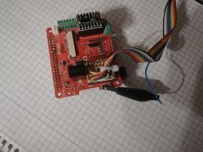
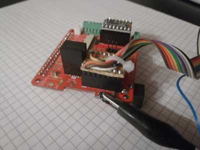
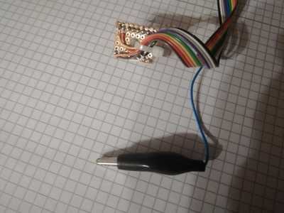
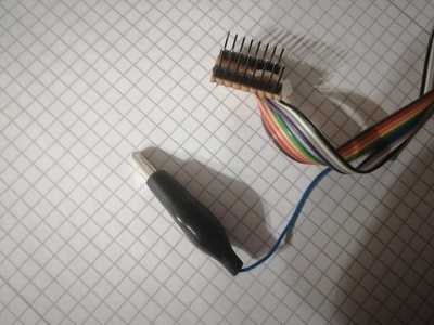
Looking at that compared to the one listed currently using a pi
You got more wires, and different locations....
I kinda wonder if something is missing from the current directions for using a pi
Is that using an Arduino?
Are they 2k and 5k
Or are they 2.2k and 5.6k
The notation means that you can use resistors with values between 2k and 5.6k.
And if the hat is connected and the pins added to the setup.... Should we be flashing it with a separate pi using the pi power supply, or just use the one your using...
Detach the HAT from the Raspberry Pi. Connect the Pi like the wiring diagram shows it. But the HAT also needs a 5V power connection.
5V Raspberry Pi < ---- > 5V HAT (e.g. VIO motor driver pin).
GND Raspberry Pi <----> GND HAT ( e.g. GND of the motor driver pin)
Tried that method
Pi and hat separated, pi powered with pi power supply , hat powered with jumpers from the pi
Still no go, the same errors consecutively... however a pi undervolt condition warning pops up on the screen after starting the process and failing the first time (second attempt undervolt)
I was just about to message watterott when they messaged me with regards to shipping 2 new boards
This is a perplexing little problem indeed
Hopefully the new boards will work out :)
The following might help to clarify a few things:
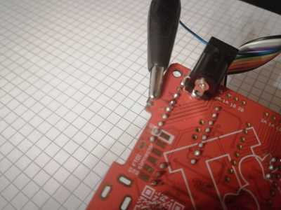
Marios photos above serve to illustrate the connections to the PI-HAT for FLASHING the bootloader. The most problematic connection is to the RESET on the PI_HAT as it isnt broken-out anywhere, it is routed to the reset switch and is tricky to solder to (hence the alligator clip). All other communication to the ATmega328 can be routed from the M3 Header (see schematic or description below). While you can use many different programmer techniques to FLASH the bootloader, the instructions from Watterott (Bootloader Instructions) use the RPI.
The following 4 data connections need to be made between the PI and the PI HAT. All data connections should use a 2.2K to 5K resistor to protect the devices from over curent. Reference Schematic .
RPi (40 pin)-> ATmega328
------------------
IO25 (19) -> Reset (PC6, pin 29 of ATMega328 attach clip on left side (40 pin header side) of reset button)
IO11 (18) -> SCK (PB5, pin 17 of ATMega328 wired to M3_DIR_D13)
IO10 (22) -> MOSI (PB3, pin 15 of ATMega328 wired to M3_EN_D11)
IO9 (20) -> MISO (PB4, pin 16 of ATMega328 wired to M3_STEP_D12)
These need to be connected if the HAT is not plugged into the PI
GND (21*) -> GND (all GND is the same on the HAT)
5v+ -> 5V+
*pi 40 pin GND on pns 2,7,11,16,21,27,32,35
If the PI_HAT is plugged into the RPI, then a provision to breakout RPI pins 18, 19, 20, 22 needs to be made. otherwise you can use jumpers from the RPI to the PI_HAT provided you include 5V+ and GND

