Hi,
Today I added a second laser to my Fabscan Pi, and I am getting wrong results. The scan from the first laser is about 10% smaller in the X and Y dimension than the scan from the second laser. The error seems to be less pronounced in the Z direction. Both point clouds are also rotated relative to each other (about 1-2 degrees).
After making sure that the lasers cross the exact center of the turn table, the camera also points exactly at the center (both with less than 1mm offset), and making sure the lasers are exactly vertical, and recalibrating, I am at a loss what else I can try.
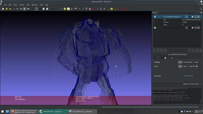
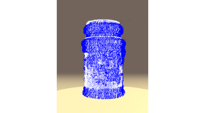
Additionally, for this model I always get points in thin air, always under the arm. I covered the model in blue spray chalk to eliminate any reflection and reduce indirect illumination, but it didn't help.
Many other parts look pretty decent, but due to these issues, the scan is ultimately unusable. I was unable to fix this up in meshlab.
It's really frustrating to have bought this device and not being able to produce a single successful scan in three years. Please help.
Today I added a second laser to my Fabscan Pi, and I am getting wrong results. The scan from the first laser is about 10% smaller in the X and Y dimension than the scan from the second laser. The error seems to be less pronounced in the Z direction. Both point clouds are also rotated relative to each other (about 1-2 degrees).
When the point clouds do not match each other, the hardware setup is not aligned correctly. Some important points are:
- check that the checkerboard sheet is in the vertical center of the calibration stand.
- the vertical green alignment line of the laser needs to hit the center of the turntable
- both lasers need to cross the center of the turntable
- both lasers should be vertical aligned on the calibration pattern
- the camera should be as sharp as possible (focus alignment)
You need to recalibrate if you change the physical setup.
Here are some helpful hints: https://fabscanpi-server.readthedocs.io/en/latest/scanner_calibration.html#laser-alignment
The calibration part is the hardest software part of this project. I am still trying to improve it. All i can say, it is possible to reach good results. Have a look at https://fabscan.org/community/general/new-software-release-v-0-8-1/ @Danilo0702 made some nice looking scans. Maybe he can share his experience.
I know that it can be frustrating when the pointclouds do not align 100%. But that is the reason why i added an option which saved a single cloud for each laser. This gives you the opportunity to merge the cloud by using CloudCompare or Meshlab.
Additionally, for this model I always get points in thin air, always under the arm. I covered the model in blue spray chalk to eliminate any reflection and reduce indirect illumination, but it didn't help.
Have you tired to use different threshold settings. Can you post some pictures of the object and your scan results please. That will maybe help me to understand what affects those points.
I tried a lot of different 3D Scanners in the last years, and out of my experience i can say that there was not a single one which was able to put the object into the scanner and getting a perfect result. Even very expensive ones. In most cases some rework on the pointcloud was required (cleaning/editing etc.)
Yes, that's what I meant. I double checked that every single point you mention is true. Any remaining deviation was way below 1mm, not noticeable to the naked eye. A second calibration run reduced the error to about 5% instead of 10%. The end result is still unusable, because there is the slight rotation offset and a tiny shift to the side as well. The latter two errors are worse than the scaling, because it's really difficult to fiddle with 5 unknown values at the same time. Do you have any ideas for that?
I am working on some solutions, for a software error correction. But i can't say when this is finished.
Looking at the results of @Danilo702 I wonder what is going wrong. There must be some other factor that also influences calibration. But it's good to see that the FabScan is able to produce good results. I need to test more...
Until that is done we need to find out what's going on ...
Regarding my model-specific troubles, yes, I have screenshots, but I don't see an option to post images here?
I think that is the Forum spam prevention feature. I just realized that your account is a fresh one. I think after a couple of posts you should be able to see the file upload Link below the text field.
Indeed, now I can attach files. I don't have a picture of the model available right now, but just look at the end of the right arm. It is supposed to be a free hanging arm. I have no idea where those few lines of dots hanging in mid air come from. They look like echos from the last correct line of the arm
Indeed, now I can attach files. I don't have a picture of the model available right now, but just look at the end of the right arm. It is supposed to be a free hanging arm. I have no idea where those few lines of dots hanging in mid air come from. They look like echos from the last correct line of the arm
That is strange. I will try to reproduce such an error. And this happens even when you used some spray on the object surface?
Actually, since the object is not terribly important to me, I could ignore this and hope this is a one-time problem. I could also send it to you so you can try yourself.
Would be an interesting option and help to find out what is going on.
Yeah, I also added a fan. It made a huge difference for scan/calibration times. I just stuck a small 40mm fan underneath and pointed it roughly at the RasPi, that was already sufficient.
I have the same issue with 2 lasers and one mesh smaller scale than the other. I have a cooling fan, so I think it is a calibration issue. Maybe my self-made calibration sheet and holder are not enough.
Can someone post the download for the original calibration sheet and holder (3D-print)? The github link from the documentation is dead...
Hi,
I recently installed a second laser. It is assumed to be an adjustable green line laser. I have no idea on how to adjust this thing. If I turn the front part it just seems to come out of the casing nothing changes to the line thickness.
Any clues on how this is supposed to work.
The other thing I'm wondering about is, that now I have a red and a green laser. Does it works ok with two colours? I don't see any possibility in the configuration file to adjust for a green and a red laser. I see only the possibility to change the number of lasers.
Regards,
Hamishi
You are able to use two lasers and you are also able to use the same laser color. But at the moment there is no option to use a different color for each. It needs to be done in Software. If you want to change from red to green you need to change the config value for the laser color:
RED
"laser": {
    "interleaved": "False",
    "numbers": 2,
    "color": "R (RGB)"
},
Green
"laser": {
    "interleaved": "False",
    "numbers": 2,
    "color": "G (RGB)"
},
Dear Mario,
Thanks for the response.
I have to buy another green one I guess. Means another 30 days waiting for delivery from China.
Regards,
Hamishi
Besides that I still have a red and a green laser, I had some advancement in the scan results. I have my 3D printer kit up and running for a while and found some interesting FabScan Pi improvements on Thinginverse, the laser towers and a stand for the calibration sheet.
I printed two towers and installed them in the FabScan, realigned the lasers and did a calibration with the old calibration sheet holder. Scan results still poor.
After that I did a calibration with the new calibration sheet holder, same sheet but upside down mounted in the sheet holder. Scan results seem very good to me now.
The two laser setup appears to be more sensitive to the placement of the calibration sheet then for a single laser setup.
This is a low resolution scan with the first laser of red color, the second laser of green color, settings of scan: no color, auto threshold, low resolution
@mario, can you explain what the effect is of setting the (RGB) parameter? From this scan it doesn't seem to matter significantly.
I also installed a fan. No more CPU throttle warnings and crashes anymore.
Hello I hope someone can help me. I am trying to get the second laser running but it never aligns with the first one. Also the first one usually has quite a bit of warp.
Am I doing something wrong? What is the accuracy someone can expect? My current software version is v.0.9.3 and I ordered the kit from Watterott.
Many thanks
Nerd


