My kit came with a 400 step motor, does this require any changes to the set up files?
My kit came with a 400 step motor, does this require any changes to the set up files?
@m.marino is right. In the past there were kits with 200 step steppers. But the default stepper is 400 steps now. And the default value in the config is 6400 steps which is for just this 400 steps steppers. But keep in mind most of the common used steppers ( for example those used in 3d printers) have 200 steps. If you have a 200 step stepper motor then you need to change the value to 3200 steps for a full turn.
Calculation for the the number of steps in the config file is:
number_of_total_steps = 16 * number_of_steps_per_turn
with 400 steps:
6400 = 16 * 400
Where 16 is the microstep level of the motor driver. Which is 1/16 step for the silent step stick motor driver by default.
I just build the kit this week and used according to the documentation the setting for a 6400 for the 400 step motor. The documentation of the motor claims that it is a 400 step motor. And that is also what I get from this forum and other people discussing this kind of problems.
The motor type is 17HM3410 delivered by Elektor, but the bag reads Watterott: Schrittmotor NEMA 17: 400 steps 42x34 mm, 2 V, 1.7 A.
So I expected to get 360 degree scans, but the scanner produced the mirrored images as can be expected with the setting 6400 and using a 200 step motor. I changed the default.config.json file setting to 3200, rebooted the pi, and scanned again.
Results look now very good, no more mirrored scans. I'm running version 0.8.2 of the server. I'm wondering if I have a wrongly labelled stepper motor or that something has changed with respect to the default.config.json configuration and the version 0.8.2.
From my set-up I cannot determine which of the two possible causes is the one.
Regards,
Hamishi
Sounds like we might have the same problem, take a look at the post, it has more detail and I agree we don't know what else has changed.
Sounds like we need to contact Watterott and see what they say.
https://fabscan.org/community/general/0-8-2-double-duplicate-scan/
Does anybody know a easy test that can be sent via SSH to test the motor steps?
No, not according to the build on the web site.
I just built the kit this week and used according to the documentation the setting 6400 for the 400 step motor. The documentation of the motor claims that it is a 400 step motor. And that is also what I get from this forum and other people discussing this kind of problems.
The motor type is 17HM3410 delivered by Elektor, but the bag reads Watterott: Schrittmotor NEMA 17: 400 steps 42x34 mm, 2 V, 1.7 A.
So I expected to get 360 degree scans, but the scanner produced the mirrored images as can be expected with the setting 6400 and using a 200 step motor. I changed the default.config.json file setting to 3200, rebooted the pi, and scanned again.
Results look now very good, no more mirrored scans. I'm running version 0.8.2 of the server. I'm wondering if I have a wrongly labelled stepper motor or that something has changed with respect to the default.config.json configuration and the version 0.8.2.
From my set-up I cannot determine which of the two possible causes is the one.
Regards,
Hamishi
Does anybody know a easy test that can be sent via SSH to test the motor steps?
https://fabscan.org/community/latest-release/communicate-with-fabscanpi-hat/#post-8
I took a look at that post right now.
According to the schematic, I think that with MS1 and MS2 at VCC the motor makes 16 steps, not 1/16. So it is, I think normal, that he measured a lower voltage with a running motor the amount of steps is also dependent on the scan resolution. A setup with a 400 step motor will be able to deliver scans with the double the resolution of a setup with a 200 step motor. This voltage should be measured with an oscilloscope by the way.
I also have a SilentStepStick TMC2208 motordriver in the setup. If the logic of the motordriver is such that it by using the MS1 and MS2 step amounts of 2, 4, 8 and 16 can be commanded, then is it understandable, that for a 400 step motor the amount of commands is double the amount of commands as for a 200 step motor. So for a low resolution scan one would send consequently MS1 and MS2 at VCC to make scan lines each 16 steps of the motor. The times that the 16 steps have to be made to complete 360 degrees is for the 400 step motor double the times as for a 200 step motor.
If I have really a 400 step motor, something in the SilentStepStick motordrive could have changed, i.e. with MS1 and MS2 at VCC it does 32 steps in stead of 16 steps as indicated in the schematic or the HAT puts VCC at MS1 and/or MS2 when it is supposed to put GND resulting in more steps then intended. But I don't think that is the case as that would result in uncontrolled turn rates of the table and that is not the case.
I don't know about a test, but if one has a confirmed 400 step motor that could be exchanged for the one in place it would be clear if the problem is in the software or in the motor.
I will see if I can contact my supplier about the possibility that the motor is actually a 200 step one and not a 400 step one as labelled.
Exactly what i came up with a couple of minutes ago, but you were faster :)
The default driver delivered with the kit should be the TMC 2100. The default config for the 400 steps stepper is set for this driver. Maybe that the 2208 has another pin configuration by default. You can find configurations for cfg pins here:
https://learn.watterott.com/silentstepstick/pinconfig/tmc2208/
and here
https://learn.watterott.com/silentstepstick/pinconfig/tmc2100/
Just looked at the minicom post.
The GO[T(400)] command would turn a 400 step motor 360 degrees and a 200 step motor 720 degrees. I'm not sure if I wrote the command correctly.
This would be a fast easy test.
GO[T(400)]
G0 T400
Ran the test and not what I expected!!
G00 T12800 F10000 is required to make the motor turn 360 degrees.
Not sure which Silentstick I have, there are no Markings on the board, but according to schematics either one uses pins MS1 & MS2 which is what my silentstick is labaled, so I assume I have a TMC2208, if it is a TMC 2100 then pins CFG1 & CFG2, which is in the same location on the board would be for the 16 microstep configuration.
Can anybody explain why it takes a T12800 to make a 360 degree move?
I have no idea. But if it is a 400 step motor your driver is making 1/32 steps. In case of a 200 step motor it is making 1/64 steps. Both values are possible with different types of the Tmc drivers.
When your driver board is from watterott, then you can match your type by the board color
https://learn.watterott.com/silentstepstick/comparison/
It seems that newer kits are delivered with the tmc2208 now. I will have a closer look to it and try to reproduce this by testing a tmc2208 in my setup. 12800 steps doesn't make sense. A scan in a low quality will take a lot of time with that. But it will increase the resolution. There is a point where a higher stepper resolution does not increase the scan resolution anymore because of the laser line thickness. The line will overlap and it will not bring more new points to the cloud.
From the comparison between the 2100 and the 2208 I observe that when the 2100 setting for 1/16 is applied to a 2208 it would probably result in 1/8. 2100 open at cfg1 and cfg2 gives 1/16 <-> 2208 low at ms1 and ms2 gives 1/8.
So there is definitely a difference between the two.
OPEN != GND
I don't know what happens to the 2208 when those config pins are OPEN. This state is not defined. Here is the TMC Datasheet.
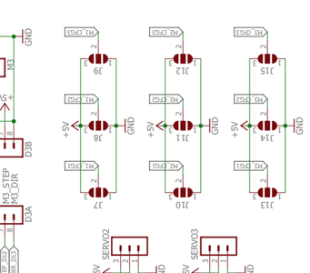
FYI here is the schematic of the HAT
https://github.com/watterott/RPi-FabScan-HAT/blob/master/hardware/RPi-FabScan-HAT_v10.pdf
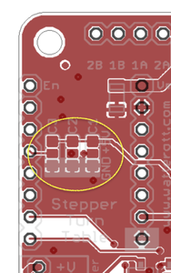
As far as i know is the default state for the 2100 on the HAT set to open. But there are onboard jumper (solder) joints which can be used to configure the motor driver. See the pictures below. You should try to set MS1 and MS2 to VIO (5V) for the 2208. This should set the diver to stealthChop 1/16 mode. ( https://learn.watterott.com/silentstepstick/pinconfig/tmc2208/ )
You should better measure which Cx on the board relates to MSx on the driver. ( I think it is mapped 1:1 e.g C1 -> MS1 but just to be sure you should use a multimeter to measure it)
Just ordered some 2208 drivers from watterott.
Can you confirm, that these pins are not driven by the software. From your replay above it seems to me that for the 21xx the default values result in the 1/16 configuration. And that for the 2208 these pins should be pulled to Vcc by soldering the bridges. I will check what is actually the case on my 2208.
If they are not driven by the software, I can pull them to Vcc by closing the bridges as indicated in the schematic. Reset the values in the default.config.json and see what happens.
Can you confirm, that these pins are not driven by the software.
Yes. The driver configuration is not software driven. Only hardware. The pads are not connected by default. So the cfg pins are in state OPEN, what fits to the 2100. I need to test the HAT with the 2208.


