Hi all,
i need some help. I am working on calibration improvements to reach better calibration results. We need to run parts of the calibration process with different positions/angles of the calibration sheet. I am already working on the software part and i am using modeling clay to hold the sheet in different positions. That works for me, but i don't think that is the best solution for all of us.
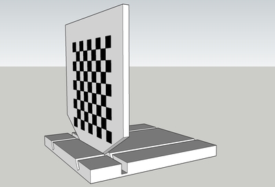
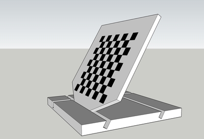
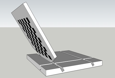
The new calibration routine will work semi-automated. The whole process will be guided. I think the first version needs some additional calibration sheet positions. A good starting point will be a tilted sheet ( -+30 degree).
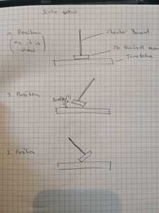
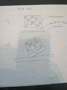
I am looking for a nifty mount design to bring the calibration sheet in different positions. Here is a hand drawn sketch which will (hopefully) illustrate what i want to reach.
The best solution would be a "one part" solution, something plugged together or maybe using magnets to hold it in position. I am completely open for your suggestions. Feel free to post your designs, thoughts or whatever might help.
Edit:
A further improvement in a later iteration would be to rotate the sheet.
Hello Mario, thanks for your Help :)
I`m testing the Hardware-Configuration of CebScan, because they use an up- and downlifting Cam, where you have an similar effekt of different Angles. I think you should also use an up- and downlifting Cam-Mount, which also can rotate it´s angle?!?
I´am only experienced in making large 3D-Models of landscapes using SFM-Software like Agisoft, with this Scanner I will made some Replicas of archeology Objekts i will use in Museum-Pedagogy, so i will need to reach a very good quality with the Scan.
Greets from Hesse
Use an Mini-Gimbal for Pan and Tilt, like this:
https://www.amazon.de/non-brand-Schwarzer-Kunststoff-Servokamera-Plattform-Schwarz-Paket-B/dp/B07YDZKZNP/ref=sr_1_26?__mk_de_DE=%C3%85M%C3%85%C5%BD%C3%95%C3%91&keywords=pan+tilt+mount&qid=1582205260&sr=8-26
I think you got more Problems with the Object to scan, when you rotate this.
Have you already considered to use an real Laser-Scanner?
For example with an Lidar-Light Sensor...
I think you got more Problems with the Object to scan, when you rotate this.
Oh maybe my description is not precise enough. I don't want to rotate/tilt the object during the scan. I want to improve the calibration process to reach a better calculation to fix the camera distortion etc. ( https://docs.opencv.org/2.4/modules/calib3d/doc/camera_calibration_and_3d_reconstruction.html )
And to reach this i need to spit the current calibration process into multiple steps where the user needs to realign the calibration tool on the turntable. I am just looking for a clever design for the printed calibration sheet foot in a way that you can place the sheet in multiple angles. Maybe this can be archived by adding some bevels to the current used STL design.
Use an Mini-Gimbal for Pan and Tilt, like this:
Not that bad but i would prefer a solution without additional electronics.
@mario , based on the sketch from your first post: if you would get an additional step motor to turn the sheet every few cm by a few degrees (20 steps left / right). this should only be connected to the sheet. (on the back) --- or manually via a gearwheel, which raises or lowers the sheed at so and so many centimeters of the turntable that the sheet tilts. That would be easy and cheap to solve without additional purchases.
German:
aufbauend auf die Skizze aus deinem ersten Post: wenn man einen zusätzlichen Stepmotor dazu bringen würde, aller paar cm in Drehrichtung das Sheet um ein paar Grad zu kippen (20 Schritte links/rechts). Dieser müsste doch nur mit dem Sheet verbunden sein. (auf der Rückseite) --- oder manuell über ein Zahnrad, was das Sheed bei so und soviel Zentimetern der Drehplatte anhebt oder senkt, so das das Sheet kippt. Man klebt eine Art Rampe auf den Drehteller und über ein Lager, was darauf läuft wird das Sheet doch automatisch gekippt. Das wäre einfach und billig ohne Zukauf zu lösen.
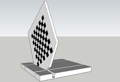
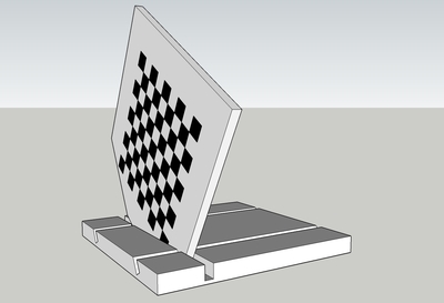
If I understand what you are asking for, would an object that incorporates a positive and negative 30° angle from the vertical plane. Which then could be set at a V going back from the planar line on the base. Utterly 3D printable and usable calibration depending on the accuracy of the 3D printer (which could be accounted with what the tolerances of dimensions should be).
Interesting idea in how to improve resolution of the scanner withing the given limits.
Right now working on understanding the wiring diagram so Th I can offer a version that reduces the board down to two motor mount points, 4 lasers, and given what has been learn here on the forum, a fan mount. Interesting discussion.
Mario, It seems the pivot point for all three positions needs to be the same. What is the optimum distance from the center of the table to the pivot point?
I use a similar calibration mount like @emw suggested for calibrating ciclop/fabscan scanners.
For general camera calibration I wrote an article about it https://medium.com/@hey_duda/the-magic-behind-camera-calibration-8596b7ddcd71 .
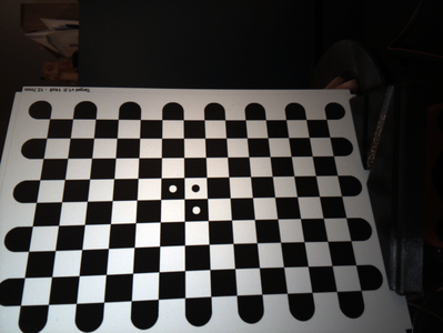
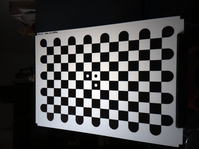
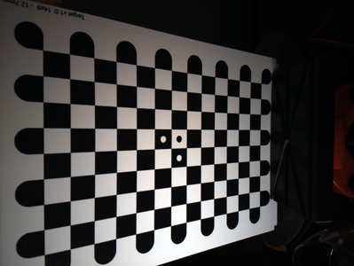
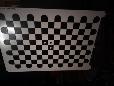
In the case of the pi camera, the following four poses are enough for good camera calibration.
For general camera calibration I wrote an article about it https://medium.com/@hey_duda/the-magic-behind-camera-calibration-8596b7ddcd71 .
Thank you for sharing this! I will give it a try.
It seems the pivot point for all three positions needs to be the same.
I am not sure. For the laser calibration step (second turn) it needs to be the same. But for the first step is doesn't matter. The most important matter is that the calibration sheet needs to be in front or behind the center of the turntable during the laser calibration step.
I think a combination of the current calibration mount and one of the shown solutions would be very nice.
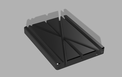
I discovered something in a video here that could perhaps be reproduced in this way. Can that work?
If that were promising, I could try to build something like that in fusion.
I discovered something in a video here that could perhaps be reproduced in this way.
Yes i am maybe we can try the good old Makerbot approach :)
I could try to build something like that in fusion.
Sounds good. It is worth to try.

