As there are no Pi Hats anymore, does anybody have the wiring for using an Arduino Uno and a A4988 Stepstick Stepper Motor Driver Module ?
I tried to wire this up like this - is this correct ?
Stepper Driver UNO
---------------- ------
Enable Pin 2
MS1 Pin 8
MS2 Pin 8
MS3 Pin 8
RST SLEEP
SLEEP RST
STEP Pin 3
DIRECTION Pin 4
VMOT 12 V Power in Nema Motor
GND GND Power In --------------
2B Black
2A Green
1A Blue
1B Red
VDD 5 Volt
GND Gnd
Pin 9 LASER +VCC
An4 LED +VCC
RE: STEPPER MOTOR CONNECTIONS AND SOMETHING TO REPLACE NON AVAILABLE FABSCANPI CONTROL BOARD
I'm having much difficulty trying to discover what is being connected to what on your information. Pictures and/or a schematic would be very helpful. More than just a stepper motor is needed as you must also control the 2 lasers and the LED.
I do not recommend using the A49898 driver module because it is quite jerky in response and can give you trouble in the accuracy of scan and stability of the object scanned. A much better choice is the TMC2100 or TMC2208. It is my understanding that the TMC2208 requires that pins MS1 and MS2 must be held high (+5v for 16 microsteps)needed for the scanner. Not sure about the TMC2100 but think the microstepper worked without any connection to those pins (at least on the PiScan board).
Following comments reflect what I think I know about the controller situation and show what I've done to date:
All controls for either the FabscanPi or the Ciclops scanners at present control the Laser 0 and 1, the LED and the stepper motor functions with an Arduino mega328 microcontroller.
The FabscanPi board is accessed through the /dev/ttyAMA0 port with I2C control. The board can deliver these control functions to any device and doesn't know if its a FabscanPi, a Ciclops or whatever.
The Ardunio with a Zum hat is accessed the /dev/USB0 port (usually or whatever usb port is on the Raspberry Pi you have). Again,the board doesn't know what its hooked to.
I suspect that the ciclops control was added to the scanner line up later than the original FabscanPi software developememt and is a result of lack of support of the ciclops team in recent years. At least I could find little if any information when I built one for the fun of it.
Considering the above, when working on my Ciclops "adventure", it was mentioned that there is difficulty in purchasing the FabscanPi control board due to availability.
I just had to try somethings. Like hoping that the correct firmware would load according to Ciclops or FabscanPi use and G code delivered to the correct port. It looks like this is true and the firmware is delivered to whatever port location determined by the information stored in the default.config.json information. The baud rates of course and other info must be correct for the port involved. The geometry and eveything else must be consistent with the machine which you are going to use.
Of course, I had to try various controls for the fun of it (maybe a little crazy too)
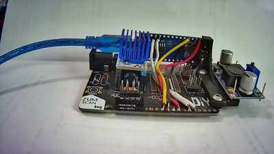
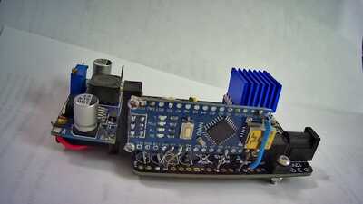
We know what the Arduino with ZUM hat does. In addition to that I tried a FabscanPi controller on the Ciclops. Watterott also has a RPI-UNO-Hat listed using I2C control protocol and port /dev/ttyAMA-perfect. I also wired an Arduino Nano to a ZUM board. They all work on the Ciclops. Each board needs the firmware loaded as dictated by the port loading requirement.
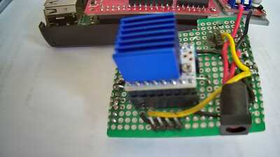
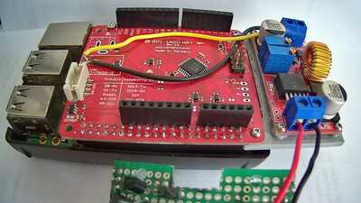
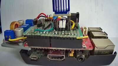
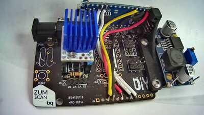
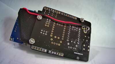
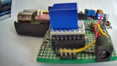
You all know what the Arduino UNO/ZUM combination and the FabscanPI controller look like. I am attaching pictures of the NANO/ZUM combo and the RPI-UNO-Hat/quasiZUM hat combo. In fact there duplicates as I am not very good at using the posting software.
The units are definitely not in a plug and play state and will need additional work to fit/use with the FabscanPi unit.
Discussion of the controller configurations:
UNO/ZUM:
The unit requires enough room that it will be difficult to place on the underside of the PiScan case (Pi board to table resting surface measures 55mm). If mounted on the back there is difficulty in routing the connections to motor, lasers and LED. Mounting below the Raspberry PI require a layout and bracket design with placement for the power connection. Height may be a problem due to clearance to the case resting surface. A short height heat sink will be necessary and possibly a special usb cable soldered directly to the Raspberry Pi tried.
NANO/ZUM
Likely the least expensive. Height not as much of a problem for installing below the Raspberry Pi. Printed bracket required to attach unit -not designed yet. Same usb cable problem as UNO/ZUM.
Fabscan Pi:
Can't buy one.
RPI-UNO-HAT/quasZUM:
Requires a Hat using the components of the ZUM hat but connects to different micro controller pins. This means it has to be hand wired on a proto board. The prototype board component locations have to be redone to fit the FabscanPi case. I think this can be done. Height (depth) of the Heat sink on the Hat is critical. Clearance should be provided to access the ICSP port as it can be used to load a bootloader if needed.
A1 pin for LED, ( #9 and #10 pins) for laser0 and laser1, #2 pin for enable, #3 pin for step, #4 pin for direction. The pin numbers are as numbered on the RPI-UNO-HAT.
I don't know the advantages of using the /dev/ttyUSB0 port vs. the /dev/ttyAMA0 port. MY only comment is our expert, Mario, chose the I2C protocol and /dev/ttyAMA0 port. So is this a great advantage?
All Arduino 5 volt regulators do not provide enough current for the raspberry pi so an external voltage step down device is required and location determined. Also, I would use active cooling which is defintely needed with the Pi4.
The micro SD card slot on the Pi is very inaccessible specially with an active cooler fan duct in place but one of the forum discussions shows an extension socket and cable which works. I boot up the Pi with a usb stick which works well (not all USB sticks will work).
Since I have certainly made 1 or 2 or MORE mistakes in my life, mistakes are very possible so please do not hesitate to inform me and this document will be corrected.
My apologies as grammar and spelling may not be my strong points as I am an old retired engineer.

